How to Build A Cedar Privacy Screen
The Privacy Screen for this deck installation went well and the client was pleased with the finished product.
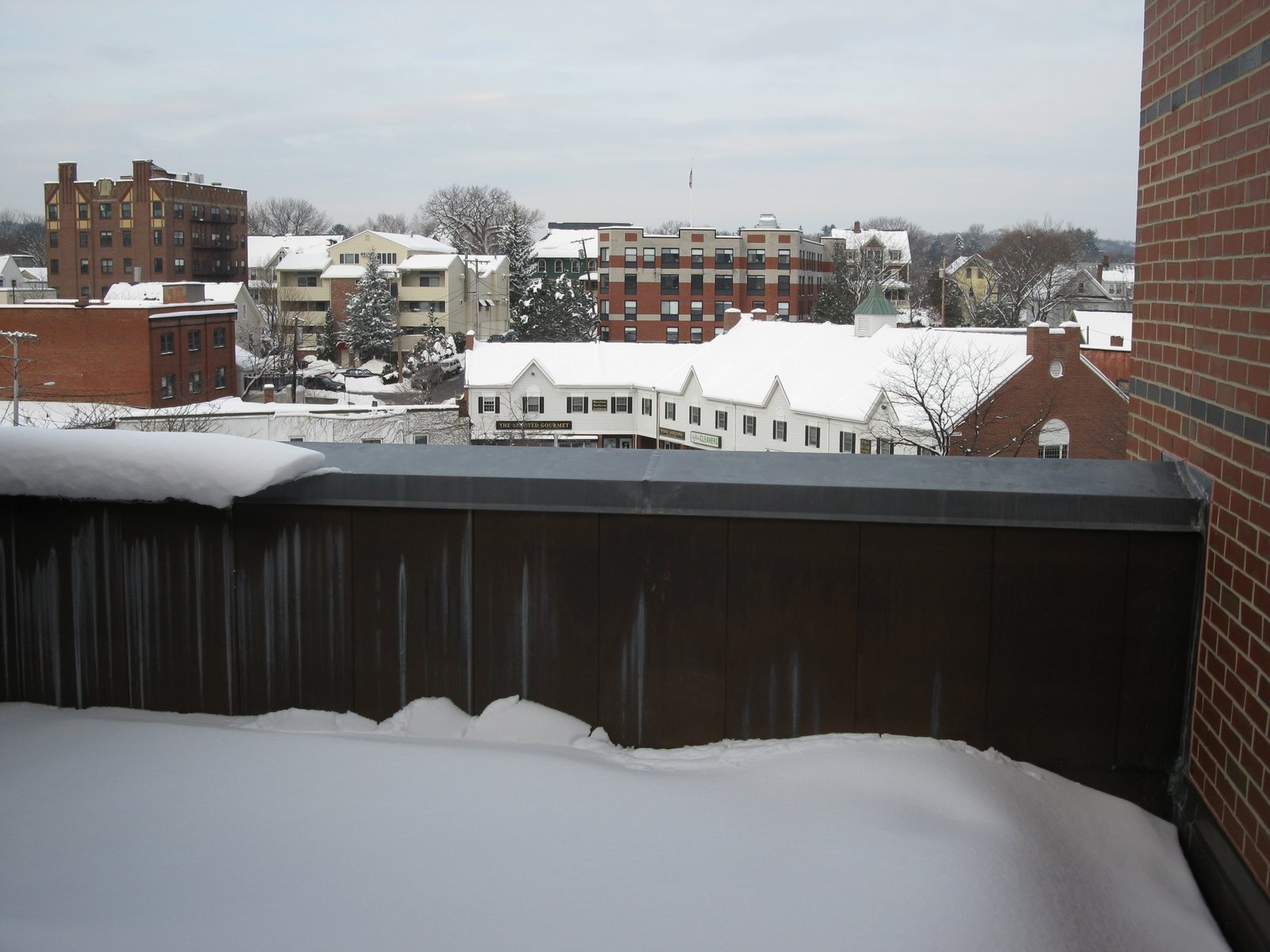
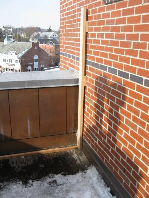
BEFORE PHOTO
Installing The Deck Privacy Screen
We build our privacy panels in the shop and transported them to the jobsite. See how we made these panels.
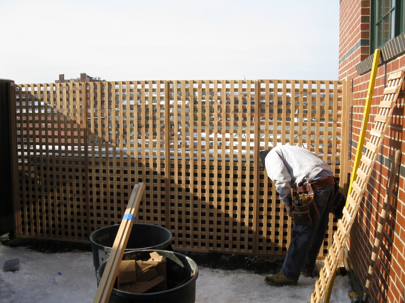
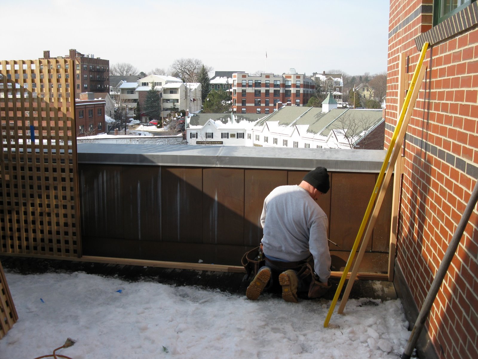
To install it we first had to deal with Mother Nature. After 1 hour of shoveling 14″ of snow off the deck, pouring hot water and chopping an inch of ice we finally made it down to the decking.
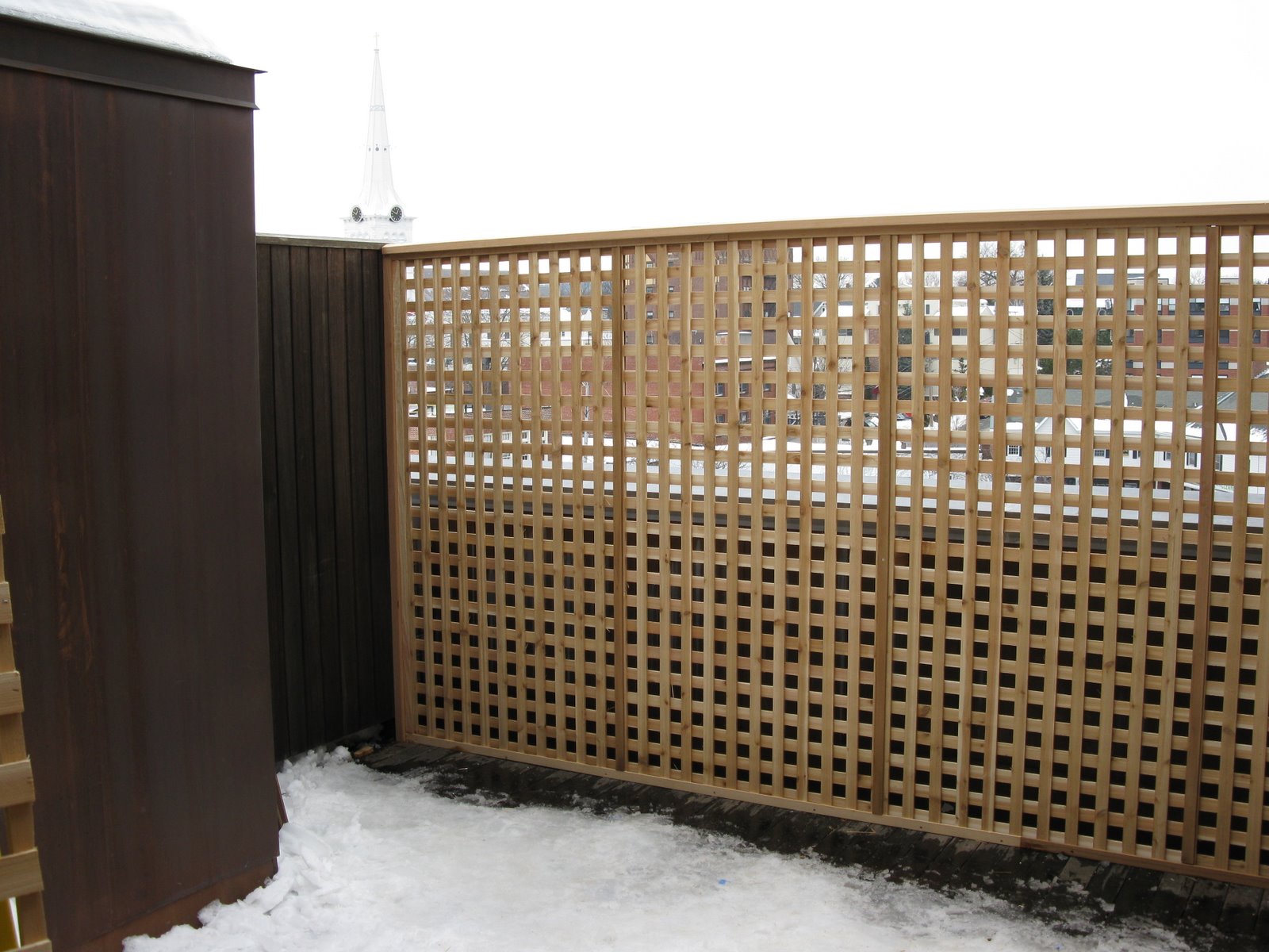
First order of business was to establish a place to install the screen. We chose to locate the screen 4″ off the rear, copper coated, half wall. [photo below]
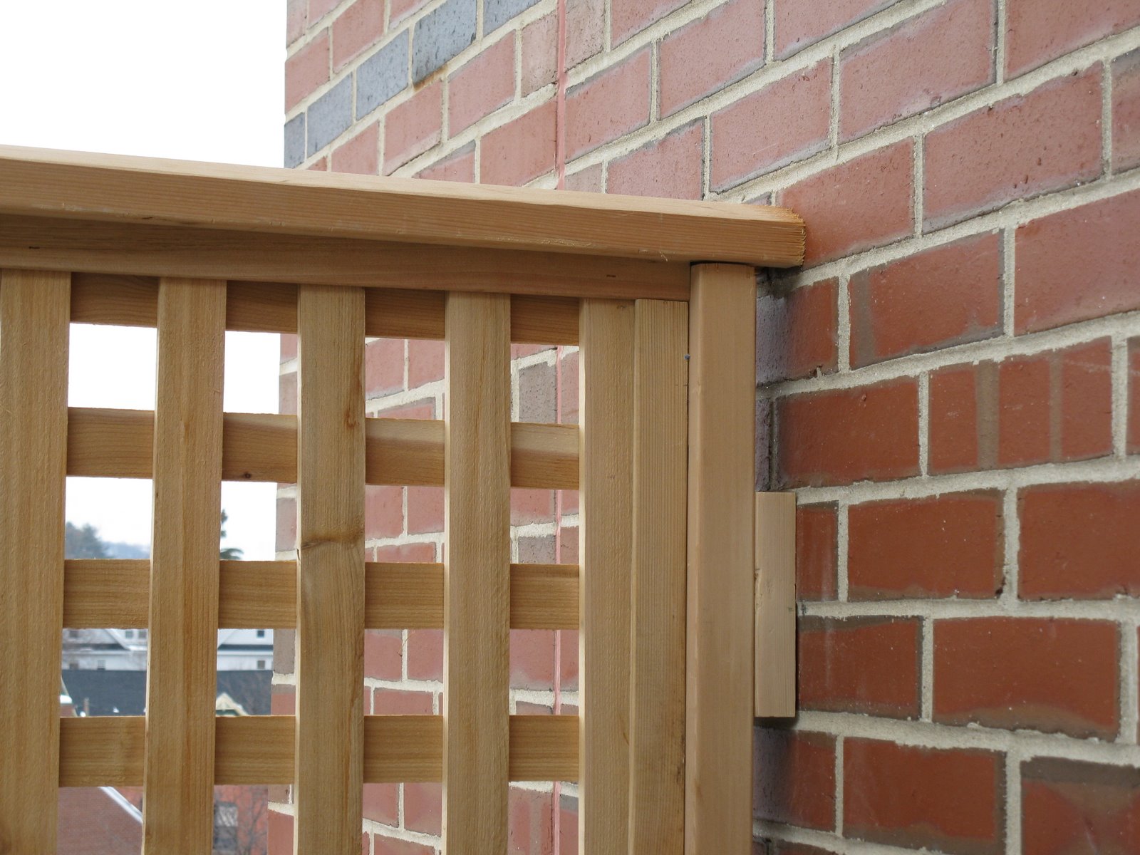
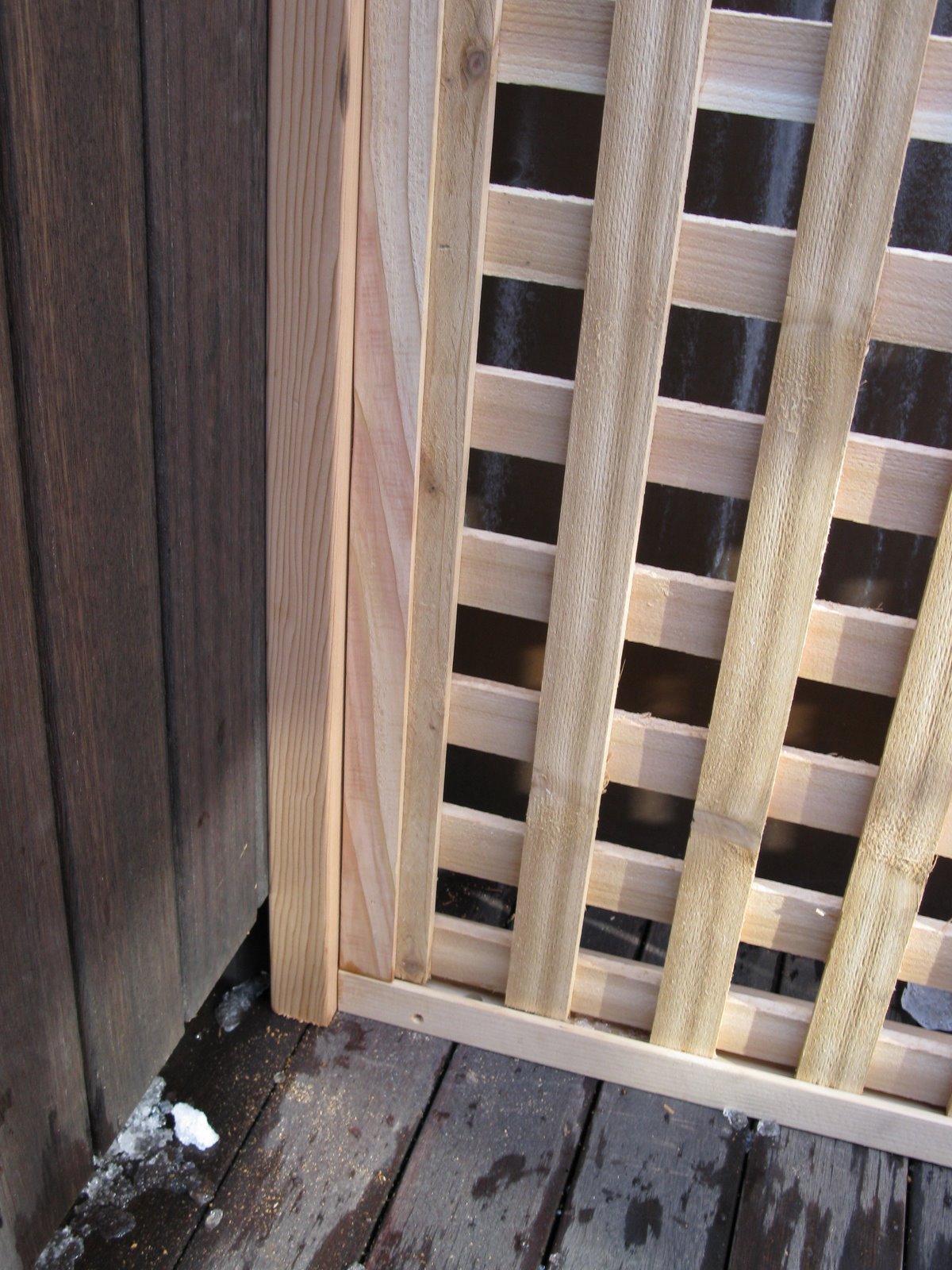
Floor Cleats and Brick Wall Provide Rigidity:
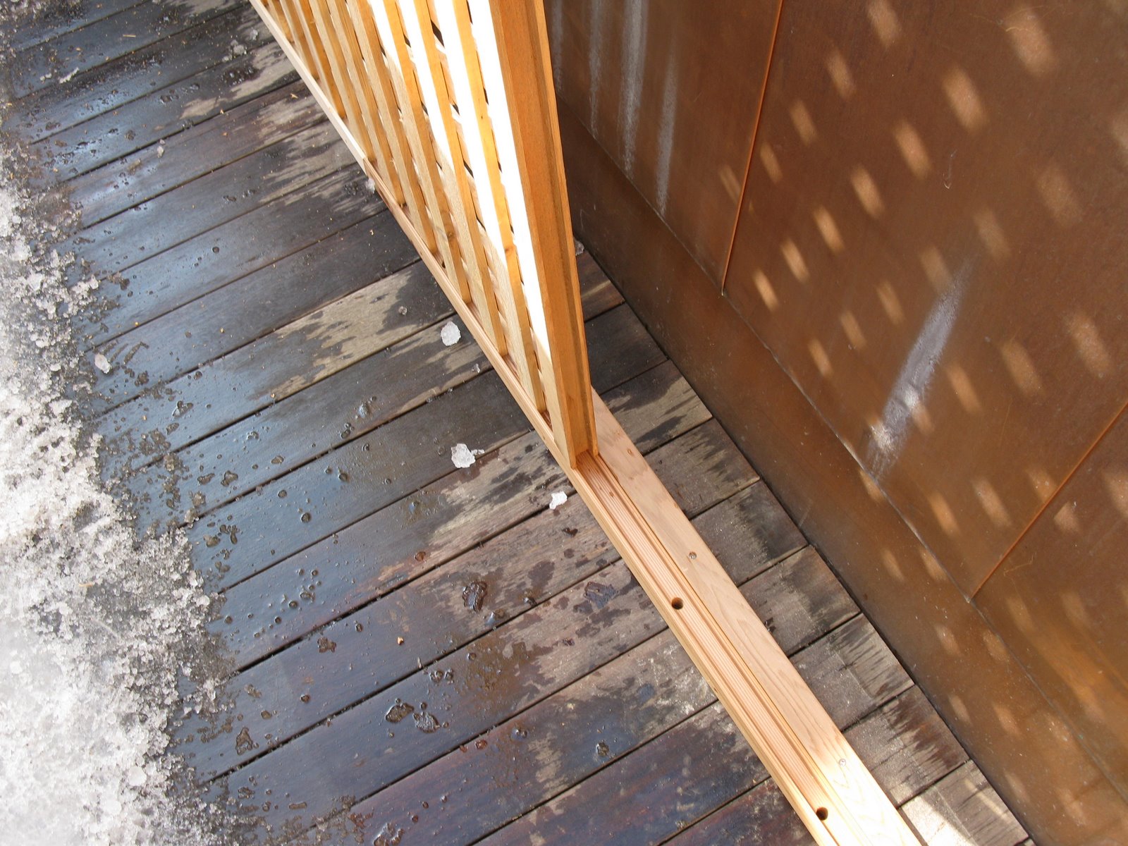
The floor cleats went in first, followed by the 2×4 wall supports.

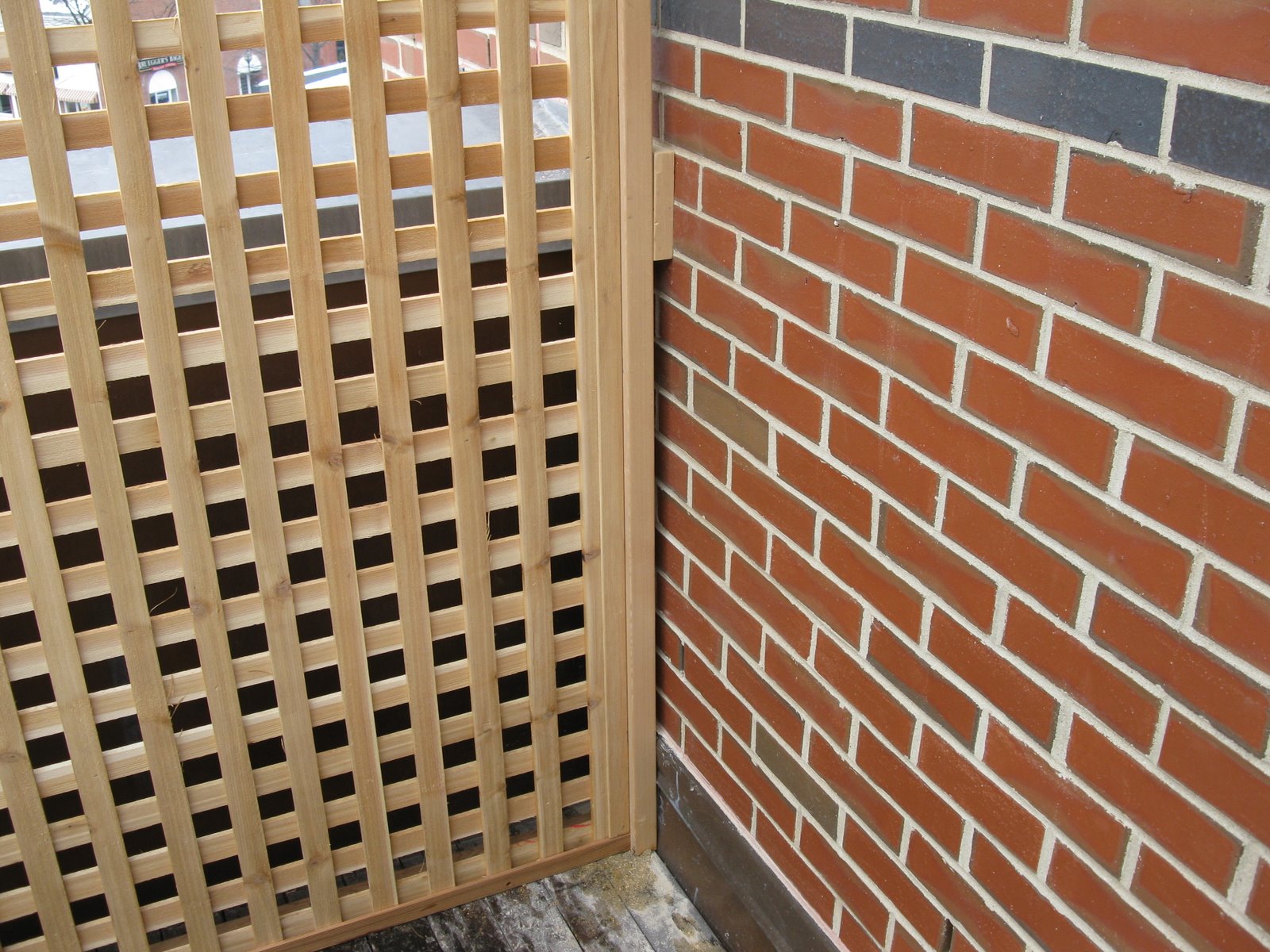
The spacer blocks were needed because of the lower portion of the wall was built out with copper counter flashing.
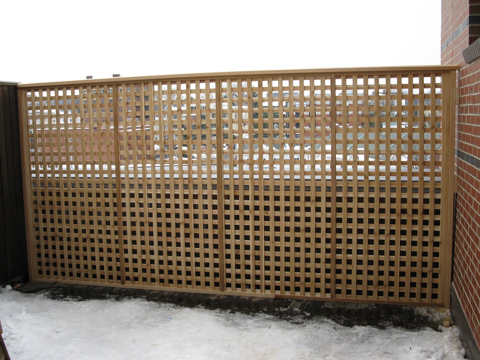
Privacy Screen for Deck

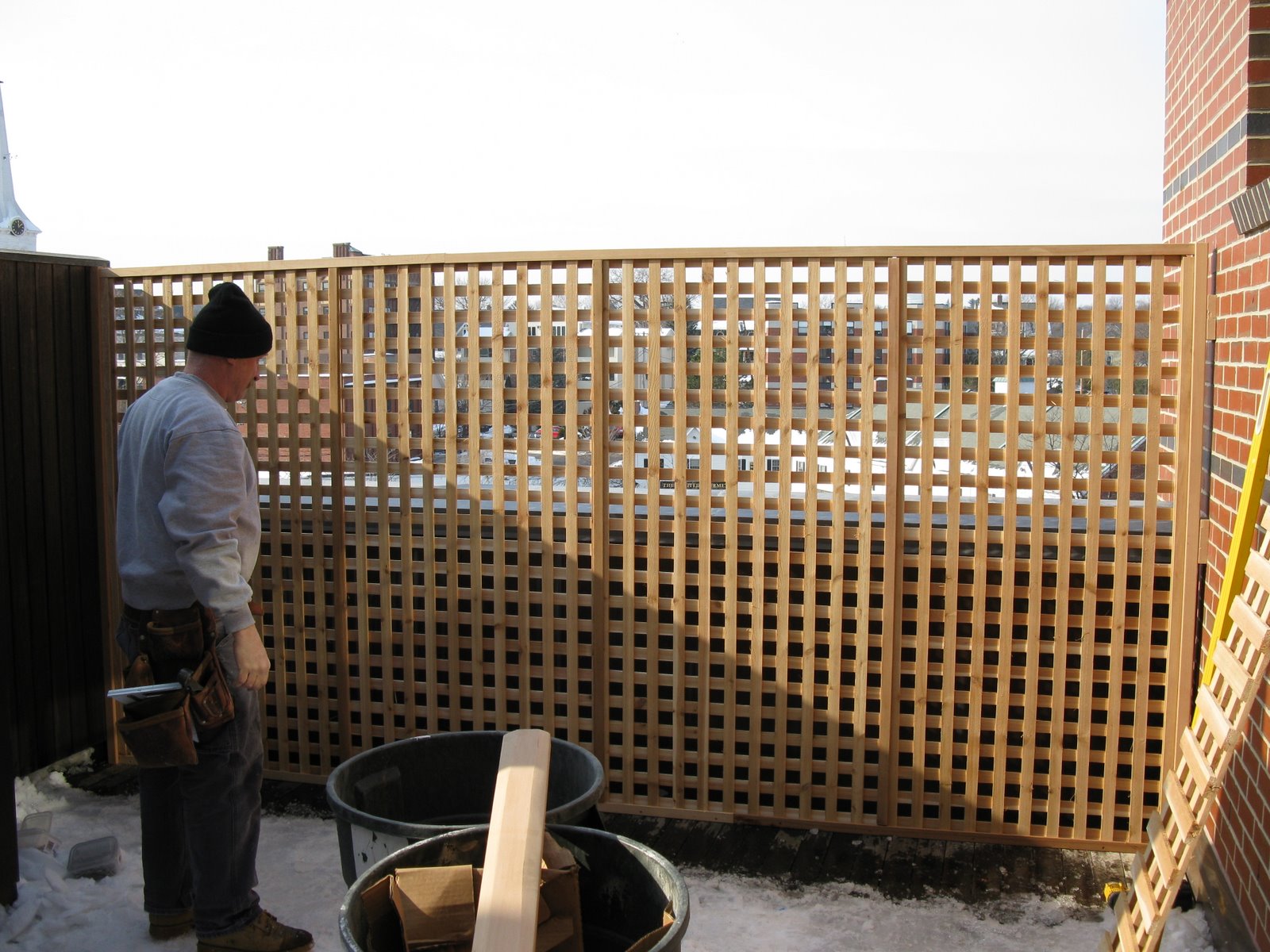
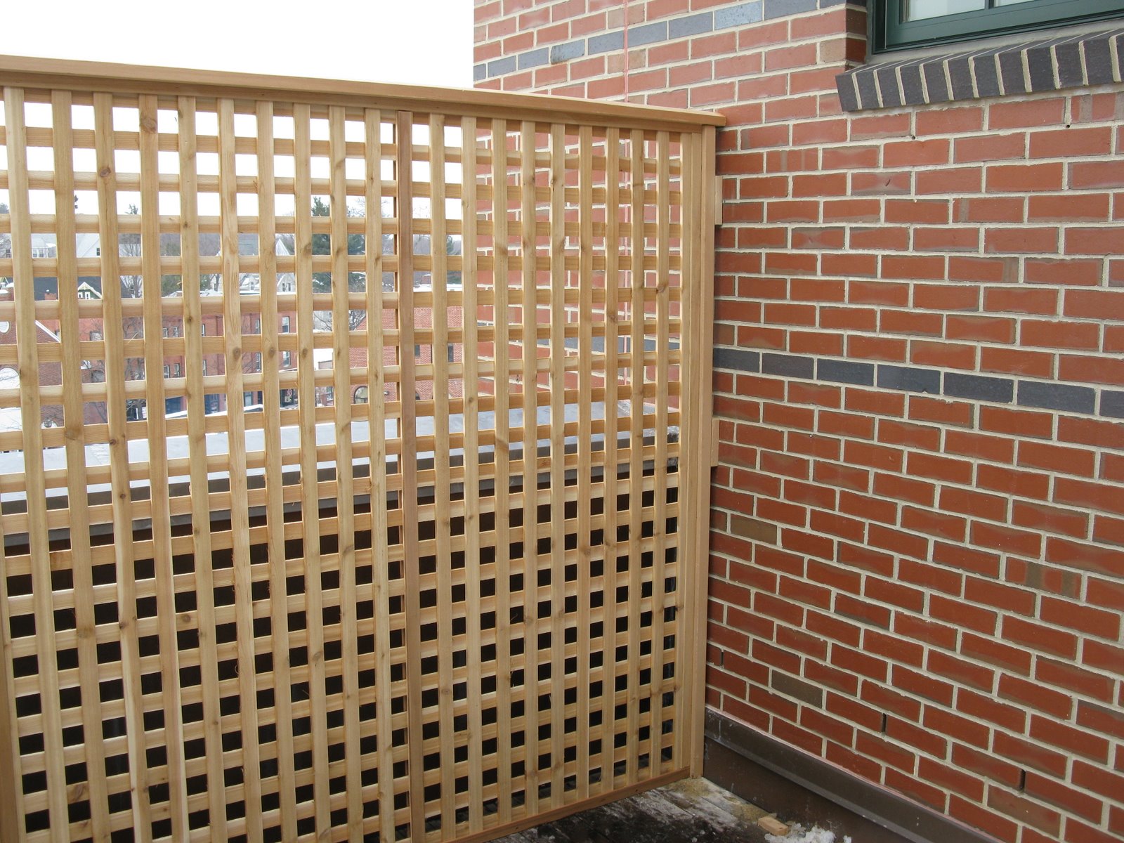
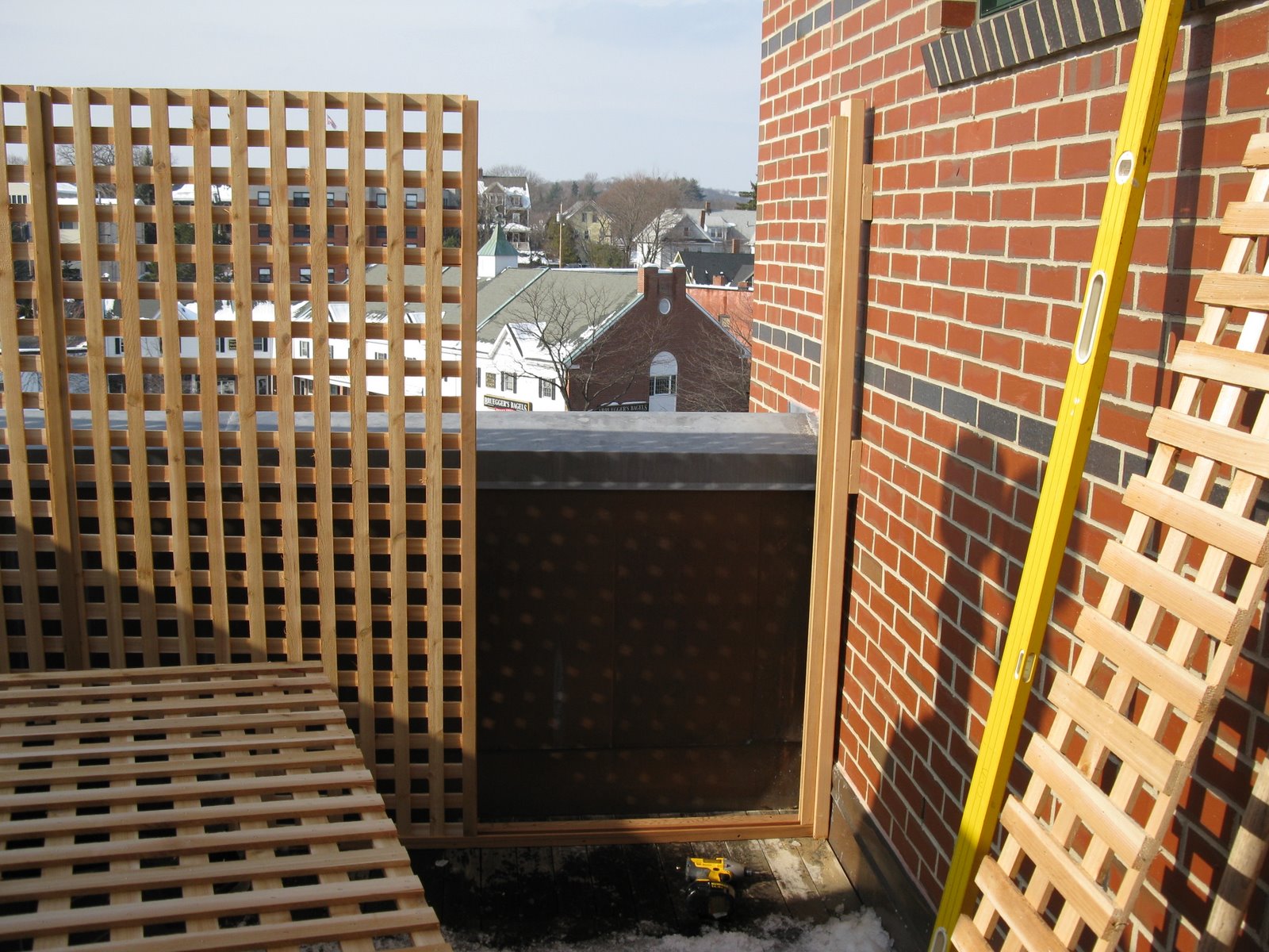
The fence 2×4 support support went up easy, was secured with hidden stainless steel screws and allowed the first panel to slip right in.
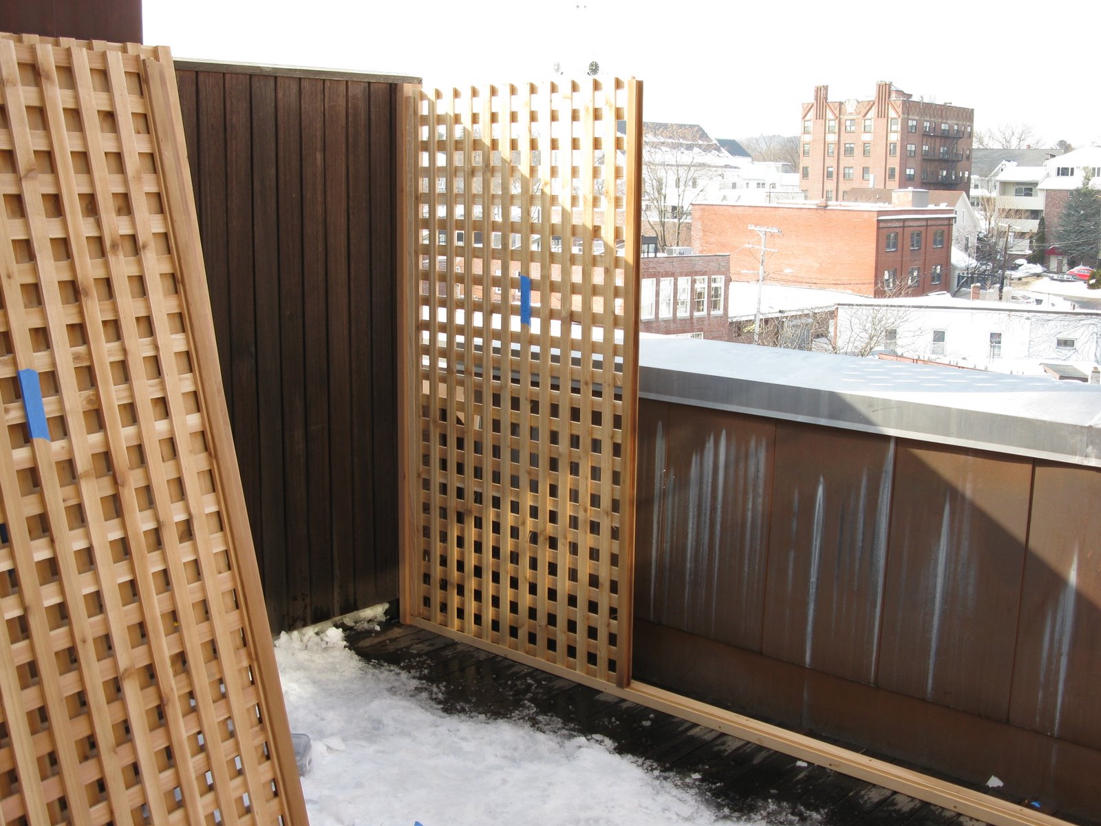
Third panel installed no issues yet. Everything was level and plumb!
Close up of the floor cleat and floor channel with drain holes.
Final panel goes in without a hitch.